Table of Contents
Plassys MEB600SL E-beam evaporator
Introduction
The e-beam evaporator is a high vacuum deposition machine that heats materials with an electron beam. Due to the heat, the vapor pressure will increase until it has reached a value above the background pressure in the chamber (~1e-8 mbar), after which the vapor particles will be forced to move due to the pressure gradient arising. This creates a flux of vapor particles moving toward a substrate. The substrate on which the vapor is deposited is roughly 60 cm away from the heated source, which allows for relatively isotropic deposition (contrary to most sputtering techniques).
The Plassys MEB600SL e-beam evaporator holds six crucibles, of which only one source can be used at a time. The crucibles typically host different materials, ranging from superconductors (e.g. Nb) to several types of ferromagnetic materials (e.g. Co, Py), adhesive/sticking layers (Cr, Ti), and capping layers (Au, Pt). The exact materials that are inside the system can vary. If you have requests, you can contact Luc Wigbout.
Some notes on requests for using materials that are currently not loaded in the system:
- If you want to know which materials are inside at this moment, feel free to ask. If you have used the system before, please check it yourself.
- If you wish to evaporate specific materials, let the technicians know (a few weeks) in advance.
- New materials are usually loaded on Friday afternoon, so please avoid booking the system on the Friday afternoon.
- Ordering new materials (that have not been used in the system) and setting up the evaporator for specific processes takes a long time. (Liner choice is far from trivial, because there is a lot of interaction between the liner and the new material. The evaporation rates at specific e-beam emission currents have to be checked. The sensitivity of the QCM measurement for specific materials is not well-documented.)
Trainings
The possible trainings for the e-beam evaporator are:
- Basic operations
- Building recipes (for more elaborate operations such as shadow evaporation)
- LN2 cooling the sample
- Refilling, liners and materials (typically for technicians)
Crucibles and liners
The crucibles are six holes in a large copper arm that is actively water cooled. In every crucible, there is a little container that holds the evaporant material. This little container is called a liner and they come in all different sorts of materials. Every material has their own preferred liner-material (e.g. Nb prefers tungsten liners over graphite due to contaminations; Au will stick to molybdenum liners, but it will form droplets in a graphite liner). Liners can come in all sorts of types: different materials1) and sizes2). If we use 4cc liners, usually there is some adapter piece involved. The wide variation in liners is because every evaporant material will behave differently in a different liner. Not only the thermal conductivity is different for every liner (which is important for the rate at which heat is dissipated from the materials), but also the interplay between liquid metal and solid liner is important (effects such as wetting, spitting, etc.)
It is good to be aware that it is very easy to burn through a liner (especially a graphite liner). Once a liner is burnt through, both the liner and the leftover material can be thrown away. 'Liner burning' can occur when the beam forms a local 'hotspot'. In order to prevent this, we have to take a look at the electron beam hitting the liner.
Electron beam
 The e-beam is emitted by a helical tungsten filament of about a centimeter long. This means that the beam itself is not very well defined, other than the emission current (typically 0-400 mA) and the voltage (10 keV).
In order to have a well-defined area that heats the evaporant material in the liner, the beam oscillates in X and Y direction with different frequencies for X and Y, creating two-dimensional harmonic oscillations also known as Lissajous curves.
This Lissajous curve has two other important features, similar to any harmonic oscillators but now in two dimensions: the amplitude and the position (absolute equilibrium position of the oscillations).
Since the X and Y frequencies have a ratio of 9:10, the Lissajous curve approaches a filled square (see Figure). So in terms of the approximated square, the amplitudes are simply the sizes of the square (height and width), while the position are the coordinates of the center of the square.
The e-beam typically provides 0-4 kW of power, heating the material over time. Heat dissipation is mainly dependent on the evaporant material and the liner. Due to the heat dissipation, the Lissajous curve becomes vaguely recognizable through the small viewport and it is good to check this during the heating of your material.
To prevent burning through liners, make sure that the amplitude of the Lissajous curve is large (typically larger than 15%) when heating up. If the material is not evaporating at the given setpoint with a high amplitude, try to lower amplitude. If the material is not evaporating at 15%, increase the current (but first increase the amplitude!). If the material doesn't evaporate at the maximum current with 15% amplitude, it is empty.
Once the material evaporates, our attention moves to the quartz crystal monitor, or Xtal monitor.
Quartz Crystal Monitor (QCM)
 To monitor the deposition rate, a piezo-electric quartz crystal, driven at a resonant frequency of 6.0 MHz, is measured while evaporating material onto it. The addition of mass causes the frequency to shift. The relation between mass and frequency change (Sauerbrey equation) is linear within shift smaller than 5% of the fundamental frequency (6.0 MHz-crystals need to be replaced before hitting 5.7 MHz). Calculating the thickness from the frequency shift of the QCM can be done using the material-dependent Z-ratio and the density.
Thus, the QCM measures the deposition rate, which, if integrated over time between opening and closing the shutter, can give the total deposited thickness. This means that the thickness itself is something relative to the start of the opening of the shutter.
To monitor the deposition rate, a piezo-electric quartz crystal, driven at a resonant frequency of 6.0 MHz, is measured while evaporating material onto it. The addition of mass causes the frequency to shift. The relation between mass and frequency change (Sauerbrey equation) is linear within shift smaller than 5% of the fundamental frequency (6.0 MHz-crystals need to be replaced before hitting 5.7 MHz). Calculating the thickness from the frequency shift of the QCM can be done using the material-dependent Z-ratio and the density.
Thus, the QCM measures the deposition rate, which, if integrated over time between opening and closing the shutter, can give the total deposited thickness. This means that the thickness itself is something relative to the start of the opening of the shutter.
All of this is done automatically in the Xtal monitor (see Fig.): by pressing Zero, the thickness is offset to 0.0 nm, by pressing Start, the same happens, but subsequently, the shutter opens and the system waits until the target thickness (nm) is reached. After the thickness is reached, it will close the shutter automatically, ramp down the emission current of the e-beam and turn off the HV.
Basic Operation Instructions
The first (safety) checks are necessary for every user:
- The three cooling water interlocks are OK.
- Cryopump is working properly (ideally, temp. 12-13 K).
- Pressures should be:
- Loadlock: ~1e-6 mbar, with the sample holder inside.
- Process chamber: <1e-8 mbar.
- The required material is loaded in the evaporator.
- You've had a proper intro to the evaporator for the process you would like to do, if not, contact a research technician.
Loading the sample
- Log in to your account on the e-beam evaporator. If you don't have one, ask for one.
- Vent the loadlock. Once the pressure gauge says 'Atmosphere', the loadlock is fully vented.
- Put on some powder-less gloves, and obtain the sampleholder from the loadlock
- Load your sample onto the sampleholder. This can be done by clamping your sample underneath the thin metal wires, with the rectangular clamps, or with the compression springs.
- Check if your samples are firmly attached by tapping on the back of the sampleholder.
- Check if the bottom of the screws do not go further than the surface plane of the back of the sample-holder (i.e. use screws that are shorter than 9 mm)
- Load the sampleholder in the loadlock, with your samples facing down.
 Make sure that the sample holder lies between the two 'fork tips'.
Make sure that the gold-coloured pin sticks through the elongated hole of the sampleholder.
- Close the loadlock with the upper turning screw.
- Pump the loadlock down to 1e-6 mbar.
Semi-Manual Evaporation
 The manual mode actually is a kind-of-manual mode, in which you operate the computer - you don't have to manually open and close the valves, the computer will control these subprocesses.
Start logging:
- In the utilities area (see Fig.), log into your account by pressing the current user name.
- Click the (2nd) button with the graph to open the graph (if this is already open, you can skip this).
- Click the (4th) button with the dark circle to open the recorder.
- Select a the relevant I/O and make a new logging file.
- Press
Executein the recorder window.
After the sample is loaded into the loadlock, and the loadlock pressure is <1e-6 mbar:
- Transfer the sample from the loadlock to the evaporation chamber. (Click
LL » Evapin the Process Diagram.)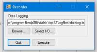
- Select the e-beam gun process.
- Orient the sample (tilt and planar rotation) to your likings.
For tilts > 45 degrees, a planar rotation of 90 degrees is required to assure that the sampleholder does not fall down in the main chamber. Take this planar rotation into account when mounting your sample.
If you tilt the sample, make sure to be in EBG mode. If you are in transfer mode, the extra 90 degree planar rotation will undo itself, and therefore the sampleholder will still fall down the main chamber.
- On the
Xtal Monitor, select the correct crucible. The crucible arm will immediately start moving after you've selected the desired material. Do not be startled by the sound. - Enter the desired thin film thickness.
- Enter a target deposition rate, a common value is 0.10 nm/s.
- Turn on the 10 kV high voltage.
- Check your material's setpoint.
- You can increase the emission current by the scrolling bar.
DO NOT drag the scroll-bar, as this rapidly increases emission current. Instead: click the ◄ and ► buttons for 1 mA steps.
- Increase the emission current slowly until you have reached the desired setpoint.
- Close the lower viewport to prevent getting welding eyes.
For some materials3) the emitted light can be EXTREMELY bright! Make sure to use eye-protection to prevent permanent eye-damage!
- Do remember to take a look at the melting material through the viewport, especially for materials with high melting points (Nb, Pt).
- When the deposition rate is close to the desired deposition rate, turn the
Rate Controlon.4) - Once your required deposition rate is reached, click the
Startbutton to open the shutter and initiate deposition onto your sample. - Write in the digital logbook, write in your labbook. Be sure to keep an eye on the emission rate.
- Once the thickness is acquired, the shutter will be closed, emission current will drop, and the HV will turn off automatically.
- Wait for 2 minutes, so that the evaporated source can cool down.
- You can either…
- … deposit another layer (go back to the crucible selection step).
- … transfer your sample to the loadlock, and unload (continue steps).
- In the Process Diagram, click the
LL « Evapbutton. - After your sample is back in the loadlock, you can vent the loadlock.
- Take the sampleholder out, using gloves.
For materials with a high melting temperature, it is good to wait some time before taking out the sample, as the holder will be warm.
- Remove your samples, and place the sampleholder in the loadlock. (It's good to be aware that some samples are clamped down so tightly, that, upon removal, they jump away like grasshoppers. Hold the sample tightly with tweezers while unscrewing the clamp-screw.)
- Pump the loadlock down.
- Leave after you see that the pressure is <1e-5.
- In the mean time, you can stop the log. As soon as you stop it, you will see in which directory it is saved. You have to open the utilities page again, and click the stripes (third button).
- Click File > Open, and select your logfile.
- Click All, click Trace.
- Now a graph with all the traced log data appears, which you can copy using the copy-icon.
- Create a new text-file and press CTRL+V to paste. (It can take a while to paste a big logfile.)
- Good luck with plotting this. It's a tab-separated file. (
 if there is a Python code available)
| Material | Setpoint | Max Emission | notes? | (date) |
|---|---|---|---|---|
| Ti | 40 | < 200 | (18 Dec. '24) | |
| Cu | 40 | < 200 | (18 Dec. '24) | |
| Au | 20 | < 40 | Graphite liners vs. Mo liners for Au | (18 Dec. '24) |
| Co | 35 | < 70 | The melting takes a while, you could increase emission to 50 mA, but the deposition rate will likely overshoot. | (21 May '25) |
| Nb | 150 | < 400 | Evaporating superconducting Nb | (18 Dec. '24) |
| Pt | 65 | < 85 | Prevent burning through 4cc-graphite liner | (10 Feb. '25) |
| Al | 50 | < 80 | (18 Dec. '24) |
Recipe-mode
Recipes can be useful for more complex processes.
To run a process with a recipe, simply follow the loading procedure described above, and click Run Process in the Process Diagram. This will open a pop-up menu in which you can select the specific recipe, and give a name to the log-file.
When you run a process, you can abort the recipe, skip steps (with caution!), or pause the process. Once you abort a process, you cannot resume it.
Ion Beam Gun
- Press
IBGmode. - Wait for the sample holder to be facing upward.
- Check that the IBG and EBG shutters are both closed.
- Wait for the turbo pump to start spinning and pumping on the chamber.
- Wait for the valve between the chamber and the cryopump to close. (Yes this is noisy.)
- Check that the MFC says 0 sccm.
- Open the Ar-valve.
- Wait until the chamber pressure is stable.
- Set your desired Argon flow (e.g. 3.0 sccm)
- Check all the settings from the ion beam (voltages, etc.)
- Press
discharge - Wait for the discharge to stabilize
- Press
beam - Open the IBG shutter and start a timer.
- Close shutter once timer is done.
- Stop beam.
- Stop discharge.
- Set argon flow to 0 sccm.
- Leave the chamber pumping until p ~ 1e-8 mbar.
- Close Ar-valve.
- Put back the sampleholder to the original position, facing downwards.
Etch rate
The etch rate in theory is about half of the etch speed of the ion beam etcher in the clean room. Beam diameter of the clean room IBG is approx. 4 cm, beam diameter of the e-beam IBG is a little below 10 cm. Beam current of the clean room IBG is ~7.5 mA, beam current in the e-beam IBG is ~15 mA.
The intensity is given as beam current divided by beam area (I/r^2π) where r is the radius of the beam (half the beam diameter).
In practice, however, the etch rate is about 1/3 the etch rate of the clean room ion beam etcher (tested 02/12/2025 with 60 nm of Nb, capped with 5 nm Pt).
Maintaining High Quality Materials
Because the system is used by a lot of users, we strongly urge every user to be aware of others' needs. After a bake-out, the pressure will be around 8e-8 mbar. After opening, the chamber always needs to be conditioned in order to obtain high quality Nb.
When materials are refilled, they need to be molten. Why do you want to melt materials loaded into the e-beam evaporator? The metals are loaded in the form of tiny pellets. These are often:
- Oxidized
- Dirty
- Thermally not well connected to each other or the liner
In the case of Nb, poor quality can be disastrous to the Tc and its applications in sample/probe fabrication. Melting it and then conditioning out the oxygen and other impurities is imperative. Increasing the heat conductance of the pellets by melting them into a single large blob makes evaporation easier and more consistent.
Melting
Different materials have different melting points, so it is important to start with a low emission current and increase it gradually depending on the targeted metal. Melting must be done homogeneously over the entire area of the liner filled with pellets, which avoids the trapping of impurities and ensures that all pellets can be combined into a single amalgamation. So the steps are:
- Write in the logbook.
- Start at 1 mA and allow the material time to heat up. The goal is to achieve a glow such that you can see where the beam aims at. (At very low currents, it is safe to remove the mask on the window for better sight). Once this is achieved at 1mA (or higher for some materials, e.g.: Nb), constantly monitor the chamber pressure. You should see a sharp increase when the material is first exposed to the beam (this is mostly oxides and dirt), which is expected.
- Now that the glow allows for orientation, you can move around with the beam. This can again result in a pressure increase. Wait until the pressure stabilizes and repeat until you have passed all the pellets. Once the chamber pressure is reduced and stabilized, you can slightly increase the current until you observe a rise in chamber pressure again (the amount you increase will likely be larger as you approach the material’s setpoint).
- Scan over all the pallets until the pressure is once again stabilized.
- Go back to step 3 and repeat until you have started evaporating some material (check the material's setpoint to get an idea of when this will happen).
Don't forget to put polarization mask on the viewport and/or welding glasses on when reaching higher currents to protect your eyes!
- The mA step size should start slowly and increase in the latter stages of the process. Use the logbook to gauge what a reasonable step should be, as melting is done with lower currents than evaporation.
Tips and tricks:
- The movement of the controller does not perfectly align with the actual movement of the beam. This results in the lower regions being unreachable via e-beam. To address this, we spend more time at the lowest point we can reach, aiming to utilize thermal conductance to melt the unreachable regions as well.
- Patience is key! Do not melt in a hurry, but relax with some nice music or company.
- In the beginning, some pallets are badly thermally connected, which sometimes causes them to be much brighter than the nearby regions. Take good care of safety for your eyes!
- Melting is done at ~e-8 mbar. During melting, it sometimes goes to e-6, but the start should have a good enough pressure to avoid more impurities.
- Throughout the melting process, the chamber pressure should never reach the ~e-5 regime. If it does, you’re either using too high of a current or melting too fast.
Aftermath
After melting, there are two important things to do:
- The conditioning of the chamber.
- The conditioning of the Nb.
Conditioning the chamber:
Evaporate a getter-material, such as Nb or Ti. These materials bond with dirt and oxygen in the chamber and end up sticking to the walls, improving pressure after pumping down again. The aim is to achieve e-9 to 1e-8 chamber base pressure..
In order to get to better pressures, one could evaporate a getter-material (e.g. Ti, Nb). This type of material will absorb vaporous hydrogen, oxygen molecules and other dirty molecules in the chamber, thus reducing the pressure further. By evaporating 5 - 10 nm of getter-material, and waiting for one hour, the chamber pressure will decrease. The aim is to achieve ~1e-8 or ~5e-9 mbar. In the first step, after some time, the getter will stop working as efficiently as in the beginning. So, when the pressure is stabilized, one can evaporate more.
Conditioning Nb:
There is still a lot of dirt in Nb after melting. This can be seen if there is a good base pressure but a very bad Nb evaporation pressure. To solve this, we evaporate a lot of Nb the get rid of the impurities. This has the double effect of also conditioning the chamber.
Building Recipes
For more advanced uses of the machine, such as shadow evaporation - where the user might want to use different tilts and angles for several evaporation steps - one can use recipes. Contact the research technician for more information about this.
Common errors
- IBG discharge failure. If the ion beam gun power source shows the HLP26 or HLP27 error, reset the power source by pressing the button the says
Discharge Enable / Standbywith the labelResetnext to it. A common cause for a discharge error is insufficient Ar pressure. A pressure of 3.8e-4 mbar is the lower boundary for a stable emission. At 3.7e-4 mbar to 3.6e-4 mbar there are insufficient Ar atoms for the IBG to maintain a stable discharge. An Ar flow rate of 3.0 sccm is sufficient, 2.5 sccm is on the lower end and might not be enough. Note: Pressure typically drops by 0.1e-4 mbar to 0.2e-4 mbar during etching over a scale of 1 to 3 minutes. Keep this in mind when selecting flow rate.
Refilling, Liners and Materials
There are several types of liners. The most commonly used liner is the graphite liner, either with or without a copper adapter. Every material uses its own liner, since the choice of the liner is material specific.
Niobium
To deposit Nb that will be superconducting, it is recommended to use 99.999% pure Nb in a tungsten liner.
Endeavors with graphite liners struggled to get a homogeneous heat distribution in the niobium pellets, and as a result the e-beam sometimes burned through the Nb and the graphite liner. The e-beam had dug a hole through the Nb and the graphite, which meant that at high e-beam emission currents not only Nb but also C would be evaporated. This ‘digging’ was a direct effect of using a liner with low thermal conductivity. Therefore, we changed to using a tungsten liner (which is known to be a high thermal conductor and has a melting point that is roughly 1000 K higher than that of Nb). Simultaneously, we got a greater ‘heat leak’, and therefore, higher beam currents had to be used.
The result was a more even distribution of heat on the Nb (surface) and effectively for evaporation this resulted in the steady deposition of Nb at low and high rates.
In order to get a deposited film of Nb that will be superconducting, the background pressure of the chamber needs to be at least <9.9e-9 mbar. During evaporation, there should be a pressure of <9.9e-8 mbar, as to ensure that there is no outgassing (e.g. air-pockets underneath the tungsten liner) that can contaminate the evaporated Nb.
In order to get a background pressure of <9.9e-9 mbar, one could condition the chamber with getter-materials.